|
|
|
ovma22xfjvs640331153.gif
 4 t @1 S! w* g
点击上方蓝色字体,关注我们$ r- p, C3 t- n8 U& n) p9 P/ N, ]
本篇博文使用ESP32-S3搭建网络摄像头,相比较局域网摄像头,本篇博文将分享如何搭建外网可以访问的网络摄像头。( g7 I8 i R6 a; K# r5 Y0 u
这主要是使用内网穿透技术,内网穿透是为了使具有某一个特定源 IP 地址和源端口号的数据包(这里指局域网摄像头)不被网络地址转换设备屏蔽而正确路由到内网主机。9 G2 K- W7 J3 i+ d# z0 Z" `
主要流程分为两步:- ?# G: v& c( q$ C9 A, E
1、先实现局域网访问网络摄像头;8 f; I9 S; |8 [1 H H" X0 ^( w% R
2、在此基础,使用内网穿透的方式,搭建外网可访问的网络摄像头。
H* ^. @2 p) T$ K0 ~' n, W1
5 D# x( \; W* o& _- s3 @局域网摄像头
6 |( Y, Z3 |: C" j% Z' kESP32实现局域网摄像头的方式比较简单,驱动代码如下:8 O. s! z7 a) I2 F+ J$ V8 R
! _) x I9 V9 J/ T8 ^#include "esp_camera.h"#include
! [4 b0 `! {" W" h* R. `//// WARNING!!! PSRAM IC required for UXGA resolution and high JPEG quality// Ensure ESP32 Wrover Module or other board with PSRAM is selected// Partial images will be transmitted if image exceeds buffer size//// You must select partition scheme from the board menu that has at least 3MB APP space.// Face Recognition is DISABLED for ESP32 and ESP32-S2, because it takes up from 15 // seconds to process single frame. Face Detection is ENABLED if PSRAM is enabled as well
1 B( y" l! u! K% n, G% G// ===================// Select camera model// ===================//#define CAMERA_MODEL_WROVER_KIT // Has PSRAM// #define CAMERA_MODEL_ESP_EYE // Has PSRAM//#define CAMERA_MODEL_ESP32S3_EYE // Has PSRAM//#define CAMERA_MODEL_M5STACK_PSRAM // Has PSRAM//#define CAMERA_MODEL_M5STACK_V2_PSRAM // M5Camera version B Has PSRAM//#define CAMERA_MODEL_M5STACK_WIDE // Has PSRAM//#define CAMERA_MODEL_M5STACK_ESP32CAM // No PSRAM//#define CAMERA_MODEL_M5STACK_UNITCAM // No PSRAM//#define CAMERA_MODEL_AI_THINKER // Has PSRAM//#define CAMERA_MODEL_TTGO_T_JOURNAL // No PSRAM//#define CAMERA_MODEL_XIAO_ESP32S3 // Has PSRAM// ** Espressif Internal Boards **//#define CAMERA_MODEL_ESP32_CAM_BOARD//#define CAMERA_MODEL_ESP32S2_CAM_BOARD//#define CAMERA_MODEL_ESP32S3_CAM_LCD#define CAMERA_MODEL_DFRobot_FireBeetle2_ESP32S3 // Has PSRAM//#define CAMERA_MODEL_DFRobot_Romeo_ESP32S3 // Has PSRAM
- T' q- ]1 N* j1 T7 D" t5 \' X9 f#include "camera_pins.h"#include "DFRobot_AXP313A.h"
" Y+ s9 ^0 ~" R4 V6 x1 M; C0 k4 s0 DDFRobot_AXP313A axp;
. @: B: b0 R% I. `$ W// ===========================// Enter your WiFi credentials// ===========================const char* ssid = "";const char* password = "";% q6 T' w% P2 ~7 H) J
void startCameraServer();void setupLedFlash(int pin);
* [7 Q* V- j/ Q, rvoid setup() { Serial.begin(115200); Serial.setDebugOutput(true); Serial.println();, T/ C$ {6 V, ~/ q
while(axp.begin() != 0){ Serial.println("init error"); delay(1000); }8 u0 z' N9 x8 m
axp.enableCameraPower(axp.eOV2640); // 给摄像头供电9 M8 {5 {7 b' N& d7 h8 E' ~- s' \
camera_config_t config; config.ledc_channel = LEDC_CHANNEL_0; config.ledc_timer = LEDC_TIMER_0; config.pin_d0 = Y2_GPIO_NUM; config.pin_d1 = Y3_GPIO_NUM; config.pin_d2 = Y4_GPIO_NUM; config.pin_d3 = Y5_GPIO_NUM; config.pin_d4 = Y6_GPIO_NUM; config.pin_d5 = Y7_GPIO_NUM; config.pin_d6 = Y8_GPIO_NUM; config.pin_d7 = Y9_GPIO_NUM; config.pin_xclk = XCLK_GPIO_NUM; config.pin_pclk = PCLK_GPIO_NUM; config.pin_vsync = VSYNC_GPIO_NUM; config.pin_href = HREF_GPIO_NUM; config.pin_sccb_sda = SIOD_GPIO_NUM; config.pin_sccb_scl = SIOC_GPIO_NUM; config.pin_pwdn = PWDN_GPIO_NUM; config.pin_reset = RESET_GPIO_NUM; config.xclk_freq_hz = 20000000; config.frame_size = FRAMESIZE_UXGA; config.pixel_format = PIXFORMAT_JPEG; // for streaming //config.pixel_format = PIXFORMAT_RGB565; // for face detection/recognition config.grab_mode = CAMERA_GRAB_WHEN_EMPTY; config.fb_location = CAMERA_FB_IN_PSRAM; config.jpeg_quality = 12; config.fb_count = 1;5 [2 }! x# ?/ K/ P
// if PSRAM IC present, init with UXGA resolution and higher JPEG quality // for larger pre-allocated frame buffer. if(config.pixel_format == PIXFORMAT_JPEG){ if(psramFound()){ config.jpeg_quality = 10; config.fb_count = 2; config.grab_mode = CAMERA_GRAB_LATEST; } else { // Limit the frame size when PSRAM is not available config.frame_size = FRAMESIZE_SVGA; config.fb_location = CAMERA_FB_IN_DRAM; } } else { // Best option for face detection/recognition config.frame_size = FRAMESIZE_240X240;#if CONFIG_IDF_TARGET_ESP32S3 config.fb_count = 2;#endif }
! u) G$ g1 M/ s8 p$ F#if defined(CAMERA_MODEL_ESP_EYE) pinMode(13, INPUT_PULLUP); pinMode(14, INPUT_PULLUP);#endif
$ v3 N( i/ D* {- r2 c! Y; c6 } // camera init esp_err_t err = esp_camera_init(&config); if (err != ESP_OK) { Serial.printf("Camera init failed with error 0x%x", err); return; }
H8 X/ h$ {3 y( K$ I) z sensor_t * s = esp_camera_sensor_get(); // initial sensors are flipped vertically and colors are a bit saturated if (s->id.PID == OV3660_PID) { s->set_vflip(s, 1); // flip it back s->set_brightness(s, 1); // up the brightness just a bit s->set_saturation(s, -2); // lower the saturation } // drop down frame size for higher initial frame rate if(config.pixel_format == PIXFORMAT_JPEG){ s->set_framesize(s, FRAMESIZE_QVGA); }. g( b/ D2 z6 l& E' V# k4 Q
#if defined(CAMERA_MODEL_M5STACK_WIDE) || defined(CAMERA_MODEL_M5STACK_ESP32CAM) s->set_vflip(s, 1); s->set_hmirror(s, 1);#endif* w. T4 }# \, d& l; r
#if defined(CAMERA_MODEL_ESP32S3_EYE) s->set_vflip(s, 1);#endif7 N& P0 t ]% j3 Z+ D8 m+ ^
// Setup LED FLash if LED pin is defined in camera_pins.h#if defined(LED_GPIO_NUM) setupLedFlash(LED_GPIO_NUM);#endif
! v7 q! `6 c/ s O( t WiFi.begin(ssid, password); WiFi.setSleep(false);( {; d7 i( d5 l
while (WiFi.status() != WL_CONNECTED) { delay(500); Serial.print("."); } Serial.println(""); Serial.println("WiFi connected");
) c5 E1 t4 Z5 [" V3 b startCameraServer();
, K4 {) r9 |+ C/ O0 l, m# } Serial.print("Camera Ready! Use 'http://"); Serial.print(WiFi.localIP()); Serial.println("' to connect");}/ ?; N% v7 t; e3 m
void loop() { // Do nothing. Everything is done in another task by the web server delay(10000);}
* _. F+ F+ i# `' F" N; J. A代码中有几点需要注意:7 e& [) a8 g3 _) X
# s m* v; J& t8 G9 a) n1、宏定义选择适配的摄像头模式。
! r5 M2 b& [1 _1 T/ r. c z) Y) n- c9 O/ Z6 c$ k# c9 f
// ===================// Select camera model// ===================//#define CAMERA_MODEL_WROVER_KIT // Has PSRAM// #define CAMERA_MODEL_ESP_EYE // Has PSRAM//#define CAMERA_MODEL_ESP32S3_EYE // Has PSRAM//#define CAMERA_MODEL_M5STACK_PSRAM // Has PSRAM//#define CAMERA_MODEL_M5STACK_V2_PSRAM // M5Camera version B Has PSRAM//#define CAMERA_MODEL_M5STACK_WIDE // Has PSRAM//#define CAMERA_MODEL_M5STACK_ESP32CAM // No PSRAM//#define CAMERA_MODEL_M5STACK_UNITCAM // No PSRAM//#define CAMERA_MODEL_AI_THINKER // Has PSRAM//#define CAMERA_MODEL_TTGO_T_JOURNAL // No PSRAM//#define CAMERA_MODEL_XIAO_ESP32S3 // Has PSRAM// ** Espressif Internal Boards **//#define CAMERA_MODEL_ESP32_CAM_BOARD//#define CAMERA_MODEL_ESP32S2_CAM_BOARD//#define CAMERA_MODEL_ESP32S3_CAM_LCD#define CAMERA_MODEL_DFRobot_FireBeetle2_ESP32S3 // Has PSRAM//#define CAMERA_MODEL_DFRobot_Romeo_ESP32S3 // Has PSRAM
5 _9 w3 W5 I/ L1 m* o0 i# p: B2、无线路由器SSID和密码要填写正确。
3 S' |: X& b" {# T; o/ M
) k3 s0 `( |+ V- K- s// ===========================// Enter your WiFi credentials// ===========================const char* ssid = "";const char* password = "";
# ^0 j; U B2 l3 g1 e4 }3、给摄像头供电, n) z9 C. C0 h' Y1 U- |
/ r* G+ o! k& x% _) [! Q
axp.enableCameraPower(axp.eOV2640); // 给摄像头供电
e9 g" ^0 ~+ r4、板卡需要外接天线,否则可能无法连接路由器。 u6 H$ e0 L' P+ P) h
! ~# A5 s: T$ X9 A编译下载程序到板卡中,确保局域网访问网络摄像头可正常使用。! E0 S+ T+ j' e
20 o" }" P: b- A$ `. Z9 M/ m
内网穿透网络摄像头+ [1 Y# }+ a; R
内网穿透我们使用花生壳这款软件提供的内网穿透服务。7 l; G' M* w$ s8 R( |
8 r4 G/ u- n4 u, o \, S
lrisokdrc20640331253.png

7 V8 e* I ^( c- G8 d3 O4 c' O; B) m# i t/ n8 B
在官网下载APP:https://hsk.oray.com/; Q& U9 m/ p4 T' }$ l. S- m& S
; o7 y$ N5 R, }/ ?# @下载安装完成后,在内网穿透服务点击新建映射,如下图所示:
$ B5 }& k, h t3 d4 f; n8 n$ x6 M# ]' g$ f+ t" E; y( K& O: e
kwppxd3ntcm640331354.png
 v8 z+ r8 F! p0 R8 L) j
$ i3 E+ e e6 N# j9 Y* F2 L2 T5 q
填写新建映射的基本信息,请注意内网主机和内网端口是局域网摄像头的主机和端口(端口默认为80) ,如下图所示:
" \ i8 d/ Q! P
- L) U8 x# L: b \; A* v# m
awcfgebibvd640331454.png
 : R* o7 m- Q6 j" ^
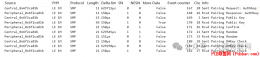
, ~9 A& k' u: f/ S: Z6 M5 R U新建映射完成后,可以在APP看到新增的设备列表,如下图所示:% M+ X2 F- o% T! [
2 g! X4 I: l, v4 Q. {, y( g v
fk5jd31l4vr640331554.png

4 n ]8 J8 r3 \! p( L9 F5 A1 \# b
复制访问网址,在浏览器中打开:http://2j90962r69.goho.co:47918/5 ?* n* h! [- L0 i
( W# B% t, E0 P, e即使不在同一个局域网内也可以正常访问摄像头啦。' B6 b9 D0 u, u
! p, e: Y$ v- ?$ c
0vcmctczypi640331654.png
 % a( U9 ?( a2 R, r* K# e6 W
, k% [( p, k0 Q* o, t3 i7 N. C) j6 s8 l0 r7 m
wmbdvo13qbs640331755.png
 - u# J3 Z6 O* w" r, u8 ^# s ^) c
往期推荐HarmonyOS学习路之开发篇—Java UI框架(Position和AdaptiveBox layout)
0 K! A5 \( W2 H3 z9 IPython数据可视化:如何选择合适的图表可视化?. o' T, w: ?8 b. K0 I2 Z2 h' G
磁耦合共振无线供电装置% _9 Q- d& U5 _3 C3 X: R% a
Python Qt GUI设计:表格和树类(提升篇—1). |9 d, |/ o* U/ @0 m5 Z2 z5 @: U
/ b& N/ h5 |+ D* s m3 x, z3 l4 z
3bs1zciapcw640331855.jpg

5 z9 K- c' x2 j4 l% O
usoexobh1wp640331955.gif
 ; i" L4 i3 S. S& B7 J' t
点击阅读原文,更精彩~ |
|


 窥视卡
窥视卡

 置顶卡
置顶卡 变色卡
变色卡